How to Fly SYMA X5SW Quadcopters for about 20 Minutes in Strong High Sky Wind

innoVolta AppNote-101

How to fly SYMA X5 series quadcopter like a Pro

The SYMA X5SW or X5SW-1 is a low cost, easy-to-fly quadcopter, which is designed for the beginners to ease their learning curve. It is easy to control in calm weather. It is light and sturdy. And, it normally does not damage even if it crashes to the ground. When a beginner gains experience or new skills, they want to eliminate the four protective arms (i.e. reduce weight by 8.0 g) so that its fly time can be lengthened a bit. They may even want to remove the video camera (i.e. reduce weight by 10.2 g) to lengthen its fly time further.

As a toy grade SYMA quadcopter, it only allows you fly for about 7 minutes even if you use an improved new LiPo battery. Another big issue is that it can not fly in high sky because it is so light and can be flipped over and crashed to the ground by wind over 5 mph. Thus, most beginners soon become unsatisfied after they gain more skills.

To resolve the users’ dissatisfaction about the SYMA toy and bring it back with a great fun again, the application engineers at innoVolta work on a solution to upgrade the SYMA toy into a professional-like quadcopter. Finally, we create two battery kits to help you fly the SYMA toy like a pro. Through a simple installation of the innoVolta IVH-1S24K1 battery kit, in 5 minutes, you are able to fly the upgraded SYMA X5 quadcopter for about 20 minutes, especially fly it stably in 50′ ~ 100′ high sky, where the wind speed can be over 20 mph often. We are going to introduce the installation procedures of the IVH-1S24K1 battery kit as follows.

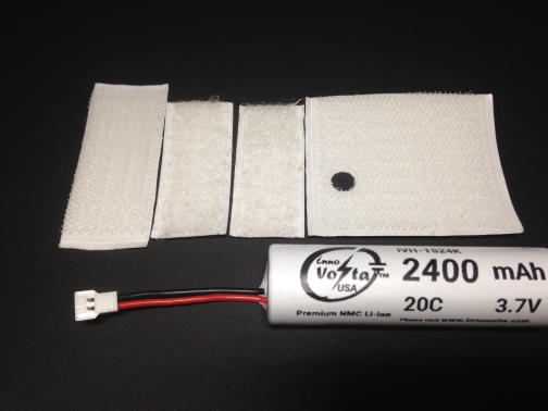
Battery Kit intro: Please refer to the following photo. The IVH-1S24K1 battery kit includes 1) a 2,400 mAh 20C high drain 18650 battery, P/N: IVH-1S24K,  2) a pair of velcro-like strips.

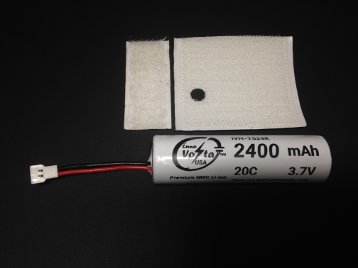
Installation Procedures: 

  1. Connect the Walkera connector to the charger provided by SYMA or an equivalent CC/CV charger, charge the IVH-1S24K high drain battery in full. [Note: The SYMA stocked charger is not a CC/CV charger! It functions like a 0.8A (max) switching power supply, which may over-charge the battery. Please monitor the battery voltage and disconnect the battery when its voltage is about 4.25 V.]
  2. Remove the video camera and the battery door. (Look for easy instructions from many YouTubers)
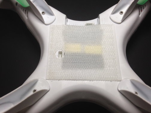
  3. Apply the “50 mm x 45 mm” velcro-like strip (with tiny flexible hooks) by pressing it tightly to the bottom center of the quadcopter as shown in the next photo.
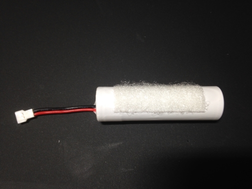
  4. Apply the “16 mm x 45 mm” velcro-like strip (with tiny filament loops) by pressing it tightly to the side center of the IVH-1S24K high drain battery as shown in the next photo.
  5. Plug in the Walkera power plug to the Walkera power socket on the quadcopter when the power switch is off.
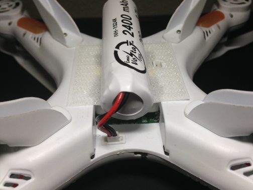
  6. Align the battery side center symmetrically to the bottom center of the quadcopter and adhere the battery to the bottom center of the quadcopter with velcro-like strips as shown in the next photo. To increase the holding reliability, it is recommended that the battery is adhered to the quadcopter’s body by adding a loop of adhesive tape. 
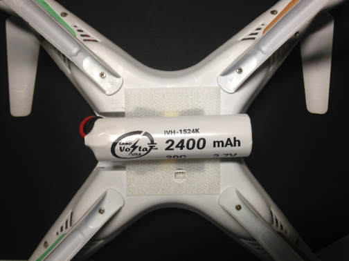
  7. Now! You are ready to fly the upgraded SYMA quadcopter like a pro. Our flying experiments show that it normally flies for about 20 minutes and can soar into the high sky and fly stably over 50′ ~ 100′  high, where normally has strong wind much over 5 mph.
  8. If you want to navigate the broad aerial surroundings, you may need the IVH-1S24K2 kit (see next photo) and use the two extra velcro-like strips to adhere the 10.2 g video camera to the bottom center of the IVH-1S24K battery. To increase the holding reliability, it is recommended that the video camera and the battery is adhered to the quadcopter’s body by adding a loop of adhesive tape.  


At present, we only develop the IVH-1S24K battery kit for upgrading the SYMA X5SW quadcopter. If you have other quadcopter and want to fly it like a pro, please contact us with your quadcopter model and tell us what functions you are seeking to upgrade your quadcopter. Our application engineers will address your requests and  provide a solution to optimize your quadcopter soon after we receive a few of upgrade requests relating to your quadcopter model. Once we initiate the R&D, we will update the status with experimental data and let you know when your desired flying goals will come true.

As a professional B2B battery pack solution provider to industrial clients, you are welcome to email your inquiry to [email protected]. InnoVolta is capable of optimizing a set of battery pack and charger to meet the strict requirement of your industrial applications.

Proper Use of Li-ion Battery Pack

Marvelous Power Comes from Proper Handling of Li-ion Battery and its Packs

Li-ion battery is becoming the most promising energy storage solution to the future. It has proved its superiority over the NiCad and NiMH batteries since its was commercialized in 1991. Nowadays, many worldwide advanced researches are still booming to improve the performance, safety, reliability and affordability of the existing Li-ion batteries. To fully utilize the tremendous  power delivered by the evolving Li-ion batteries, users should understand how to handle it properly. We are describing some useful information from battery cell to battery pack for your reference below.

Cell Charging:

  • A CC/CV (Constant Current / Constant Voltage) charger is required for charging a Li-ion cell. Unless a cell is specially specified, the charging voltage of a normal Li-ion cell is limited to 4.20 V/cell. Over-charging a Li-ion cell will reduce its nominal capacity and obviously shorten its cycle life. A Li-ion cell may be excessively charged if it is left on a charger unattended for long time, and it may lead to cell failure or a serious safety issue!
  • Never use a DC power supply to charge a Li-ion cell because a continuous charging device will over-charge the cell with trickle currents. When a Li-ion cell is fully charged at 4.20 V/cell, the charging current should be completely cut off when the charging current drops below 0.02C level.
  • The standard charging current is o.5C after a Li-ion cell is discharged and its OCV (Open Circuit Voltage) is above 3.0 V. The OCV of an aged cell may stay below 3.0 V after excessive discharge. For such a case, a pre-charge at 0.1C is required before its OCV rises over 3.0 V. Dispose a Li-ion cell if its OCV no longer exceeds 3.0 V.

Cell Discharging:

  • The discharge current must obey its specification. Never abuse a Li-ion cell by discharging it over the specified continuous maximum discharge current.
  • The discharge voltage must obey its specification. Never abuse a Li-ion cell by discharging it below 2.0 V.
  • Use caution to monitor the body temperature of a Li-ion cell when it is drained at high current. A Li-ion cell will shorten its life if you allow its body temperature to rise over 60 degree C.

Storage:

  • A Li-ion cell should be stored in a dry area without any corrosive gas.
  • It requires paper board crate to store each cell separately in a sturdy box so that no excessive mechanical force can shock or deform the cells in storage.
  • The ambient temperature from -10 ~ +25 degree C is proper for long-term storage (e.g. 12 months). Wider temperature range from -20 ~ +45 degree C is also acceptable for a short-term storage (e.g. 3 months).
  • The SOC (State of Charge) of Li-ion cells should be controlled between 40% to 50% before they are put into storage.

Cycle Life:

  • If a Li-ion cell is charged and discharged per its specification, it will deliver the promised cycle counts and capacity level according to its cycle life test data.
  • Deep cycles are not suggested for the normal use of a Li-ion cell or pack unless it is necessary for a special application. Reduce the voltage swing will optimize the cell performance and lengthen its life.
  • Cycle life of a Li-ion cell is determined by the conditions of charging, discharging, operating temperature and storage.

Battery Pack Design:

  • The design of a Li-ion battery pack must consider a structure that can effectively prevent water and static charges from spreading through around the assembled cells.
  • If a PCB/PCM (Protection Circuit Board/Module) is required to be assembled with cells, the leakage current must be less than 1 micro Amps and the short circuit protection must be detected less than 0.5 ms (shorter detection time is better). Other features like over-voltage protection, over-discharge protection, and over-current protection should be considered, too.

Battery Pack Assembly:

  • The usage of damaged cells must be prohibited! Never use abnormal cells, which have been damaged during the transportation. Damaged cells may be resulted from over stress or deformed housing, short circuit, twice spot welded, or venting with electrolyte odor.
  • Inspect OCV, IR (Internal Resistance) and Capacity before doing the cell assembly. Only precisely matched cells are allowed to be assembled into battery packs.
  • Use spot welder and nickel strip or plate to connect cells in series or in parallel. Never solder directly onto a cell, which may be damaged by the overheat!
  • Accidental short circuit may occur during the pack assembly. It is dangerous and may hurt the operators. Proper wiring layout and assembly procedures must be integrated into well-trained workmanship to effectively avoid any possibility of a short circuit.